Monday, September 17, 2012

DFT and IDFT using MATLAB


AIM:
To find DFT and IDFT of a sequence.
APPARATUS REQUIRED:
Hard ware: IBM PC or compatible
Soft ware : Matlab 6.5 or higher
THEORY:
In mathematics, the discrete Fourier transform (DFT) is a specific kind of discrete transform, used in Fourier analysis. It transforms one function into another, which is called the frequency domain representation, or simply the DFT, of the original function (which is often a function in the time domain). The DFT requires an input function that is discrete. Such inputs are often created by sampling a continuous function, such as a person's voice. The discrete input function must also have a limited (finite) duration, such as one period of a periodic sequence or a windowed segment of a longer sequence. Unlike the discrete-time Fourier transform (DTFT), the DFT only evaluates enough frequency components to reconstruct the finite segment that was analyzed. The inverse DFT cannot reproduce the entire time domain, unless the input happens to be periodic. Therefore it is often said that the DFT is a transform for Fourier analysis of finite-domain discrete-time functions.
FFT algorithms are so commonly employed to compute DFTs that the term "FFT" is often used to mean "DFT" in colloquial settings. Formally, there is a clear distinction: "DFT" refers to a mathematical transformation or function, regardless of how it is computed, whereas "FFT" refers to a specific family of algorithms for computing DFTs. The terminology is further blurred by the (now rare) synonym finite Fourier transform for the DFT, which apparently predates the term "fast Fourier transform"
The discrete Fourier transform (DFT) is given by:
The inverse discrete Fourier transform (IDFT) is given by:

PROGRAM:
clc;
clear all;
close all;
x=input('enter the sequence');
x1=fft(x);
subplot(2,2,1);
stem(imag(x1));
title('imaginary fft');
disp('fft');
disp(x1);
subplot(2,2,2);
stem(real(x1));
title('real fft');
y=ifft(x1);
 subplot(2,2,3);
stem(imag(y));
title('imaginary ifft');
disp('ifft');
disp(y);
subplot(2,2,4);
stem(real(y));
title('real ifft');


Enter the sequence     [1   2   3   4]


Tags: MATLAB basics, MATLAB programs, MATLAB signal generation, Learn MATLAB, IDFT, DFT, IDFT using MATLAB, DFT using MATLAB, IDFT programs, DFT programs, IDFT and DFT programs 
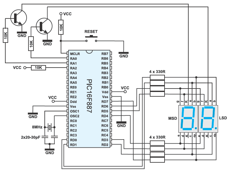
Two-digit LED counter using PIC


Here the PIC16F887 is used as a two-digit counter . The variable i is incremented (slow enough to be visible) and its value is displayed on a two-digit LED display (99-0). The challenge is to enable a binary number to be converted in decimal and split it in two digits (tens and ones). Since the LED display segments are connected in parallel, it is necessary to ensure that they change fast in order to make impression of simultaneous light emission (time-division multiplexing).
In this example, timer TMR0 is in charge of the time-division multiplexing, while the mask function converts a binary number into decimal format.
Example 9
/*Header******************************************************/
    
unsigned short mask(unsigned short num);
unsigned short digit_no, digit10, digit1, digit, i;

void interrupt() {
    if (digit_no==0) {
        PORTA = 0;                 // Turn off both displays
        PORTD = digit1;            // Set mask for displaying ones on PORTD
        PORTA = 1;                 // Turn on display for ones (LSD)
        digit_no = 1;
    } else {
        PORTA = 0;                 // Turn off both displays
        PORTD = digit10;           // Set mask for displaying tens on PORTD
        PORTA = 2;                 // Turn on display for tens (MSD)
        digit_no = 0;
    }
    TMR0 = 0;                      // Reset counter TMRO
    INTCON = 0x20;                 // Bit T0IF=0, T0IE=1
}

void main() {
    OPTION_REG = 0x80;             // Set timer TMR0
    TMR0 = 0;
    INTCON = 0xA0;                 // Disable interrupt PEIE,INTE,RBIE,T0IE
    PORTA = 0;                     // Turn off both displays
    TRISA = 0;                     // All port A pins are configured as outputs
    PORTD = 0;                     // Turn off all display segments
    TRISD = 0;                     // All port D pins are configured as outputs
    
    do {
        for (i = 0; i<=99; i++) {  // Count from 0 to 99
            digit = i % 10u;
            digit1 = mask(digit);  // Prepare mask for displaying ones
            digit = (char)(i / 10u) % 10u;
            digit10 = mask(digit); // Prepare mask for displaying tens
            Delay_ms(1000);
        }
    } while (1);                   // Endless loop
}
mask.c file:
/*Header******************************************************/
unsigned short mask(unsigned short num) {
switch (num) {
case 0 : return 0x3F;
case 1 : return 0x06;
case 2 : return 0x5B;
case 3 : return 0x4F;
case 4 : return 0x66;
case 5 : return 0x6D;
case 6 : return 0x7D;
case 7 : return 0x07;
case 8 : return 0x7F;
case 9 : return 0x6F;
}
}

Sunday, September 16, 2012

LCD based digital alarm clock using 89S51 MC

LCD based digital alarm clock using 89S51 MicroController

 
 Circuit Diagram
An alarm clock is a clock that indicates a pre-set time by producing sound at that time. This functionality of digital clock is used to awaken people or remind them of something. A digital clock is one that displays time digitally. The project explained here, displays time on a 16x2 LCD module. The LCD is interfaced with 8051 microcontroller (AT89S51). This circuit can be used in cars, houses, offices etc.


Read Full Article 


Tags: microcontroller projects, digital alarm, 89S51 microcontroller, 89S51 microcontroller projects, 89S51 microcontroller circuits, project circuits