MINI SPY ROBOT
Introduction
The
Mini Spy Robot is small robot with a camera attached to it. The main parts are
the body of robot, remote and a CCD camera. The body of the robot consists of
two wheels attached to geared motors and these motors are controlled by the
remote. The remote is placed inside a wrist watch. Using the 4 switches of the
watch the movements of the robot are controlled. The robot can be moved forward
and backward and also it can be rotated left or right. The video signals which
are transmitted from the camera are viewed in a laptop or TV.
VOLTAGE REGULATOR
The IC is used as the voltage
regulator. It converts the 6V supply into 5V regulated supply
ENCODER
The
IC HT12E is used as the encoder. It converts the input pulse into binary
signals and it is given to the transmitter..
ASK TRANSMITTER
The ASK transmitter is a 433 MHz
Radio Frequency signal transmitter. ASK is short for Amplitude Shift Keying. It
modulates the binary signals into analogue signal.
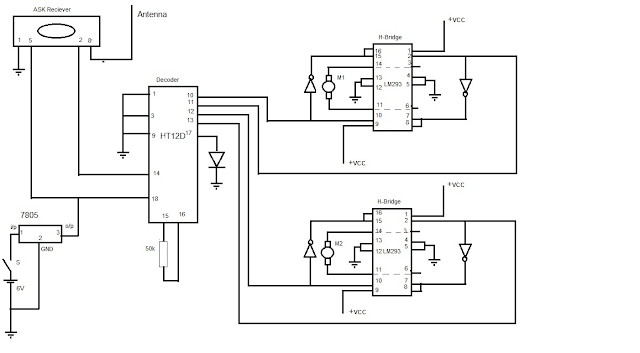
ASK RECIVER
The
ASK receiver receives the binary signals transmitted by the transmitter. It
demodulates the received analogue signal into binary signal.
DECODER
The
IC HT12Dis used as decoder. It decodes the binary signal.
H-BRIDGE
The
IC L293D is used as the H-Bridge. It is
used to change the direction of rotation of the motor with respect to the input
signal.
CAMERA
The
camera is a wireless CCD camera. It works on 12V dc supply. It transmits the
captured videos. The receiver receives those signals and produces an A/V output
and it can be connected to a TV or a Laptop.
TRANSMITTER
RECIEVER
WORKING
The
mini robot has two circuits, one for the remote section and other for robot
section. The basic working of the robot is that, when the switch in remote is
pressed then a signal is produced and it is then encoded and then modulated and
transmitted to the robot and the receiving section demodulate and decodes the
signal and the signal in remote is reproduced in the receiving unit. This
signal is applied to the motor through an H-bridge.
Here
we use HT12E and HT12D as the encoder and decoder. They have 8 bit address and
4 bit data. Hence we can transmit 4 signals for the four type movements of the
robot such as forward, backward and turn left and right.
Now
consider the remote section .The main elements in the remote section are an
encoder IC, an ASK transmitter and four switches. The encoder IC has 18 pins. The
pins one to eight are the address bits. The four pins, pin no.8 to 13 are the
data bits or input terminals. These four pins are connected to the four
switches. When a switch is closed, that pin is grounded. Thus a signal is
produced and the encoder converts it into binary signal and this binary signal
is modulated and transmitted by the ASK transmitter.
Now
consider the receiver section. The signal is received and demodulated by the ASK
receiver and this binary signal is given to the decoder. The decoder converts
it into actual signal corresponding to the pin in encoder, the same pin
produces a ground signal while the other data pins produces a +VCC as output.
The output from the data pins are applied to the H-bridges. Each H-bridge has
two halves.
The
outputs from pin number 10 and 11 are given to the first H-bridge. If the pin
number .10 produce a ground signal then the left half of the H-bridge become
enabled and rotates one motor forward. If pin no.11 produces a ground signal
then the right half of the H-bridge becomes enabled and rotates the motor
backward.
As
illustrated above, the pin.no.12 and 13 are applied to the second
H-bridge. Thus the second motor rotates
in the direction with respect to the signals from pin no.12 and 13.Thus if the
pin 10 and 13 are grounded in remote the robot moves forward and if 11 and 12
are grounded then the robot moves backward.
To turn the robot left, pins 11,13 are grounded
and to turn right, pins 10,12 are grounded.
COMPONENTS PRICE LIST
COMPONENTS
PRICE QUANTITY TOTAL
IC HT12E 48 1 48
IC HT12D 55 1 55
IC LM 7805 12 1 12
IC L293D 70 2 140
IC 7404 10 1 10
RF MODULE 285 1 285
WRIST WATCH 100 1 100
LED 3 2 6
RESISTOR 4 2 8
CMOS CELL 15 2 30
6V CELL 240 1 240
CCD CAMERA 1600 1 1600
GEARED MOTOR 100 rpm 148 2 296
ROBOTIC WHEELS 80 2 160
PCB 250
TOTAL 3240.00
Tags: robotics, simple robot, spy robot, robot with camera, ccd camera, spy camera, remote controlled robot, spy circuits, circuits with HT12E, circuits with HT12D, rc robots, two wheeled robots, robot circuits, mini robot projects, low cost robots, geared motor, RF modules, IC L293D circuits, hobby projects, mini electronics projects, mini projects without micro controller, hobby circuits, spy works, spy gadgets, motor related, motor driving circuit, rc motor control, remote controlled motor, RF module projects, RF module circuits.


